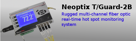
T/Guard-2B Smart Grid monitoring system
Description

- Small and sturdy enclosure
- Tough and ruggedized sensors
- No gage factor or calibration
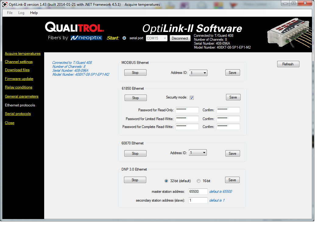
- Serial communication: RS-485, IEC 61870, MODBUS and DNP3
- Ethernet communication: HTTP, MODBUS, IEC-61850, IEC-60870, DNP3
- 4 GB internal datalogging memory
- Accuracy of ±1 °C
- 15 built-in Form-C relays (remotely located)
- 1 built-in system fault relay
- Available with 4 to 16 channels
- Detachable connector blocks for easy installation
- Quick and easy web-based configuration, in 12 languages (Arabic, Chinese, German, English, Spanish, French, Italian, Japanese, Korean, Polish, Portugese and Russian)
- Compatible with OptiLink and OptiLink-II softwares
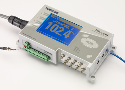
The Neoptix T/Guard-2B is a full featured smart grid ready multichannel fiber optic system for high voltage and transformer hot spot temperature measurement
For a product brochure of the T/Guard-2B Signal Conditioner, please contact Neoptix
The Neoptix™ T/Guard-2B™ is a multichannel fiber optic temperature monitoring system for power transformer hot spot measurements. The T/Guard-2B system has been developed with long-term performance and stability in mind. This fiber-optic temperature monitoring system for power transformers offers accuracy, toughness and long-term resistance to failure.
Coupled with the T/Guard-2B system, the Neoptix T2™ fiber-optic temperature probes provide accurate and direct temperature monitoring of transformer windings. This solution provides a realistic, real-time view of winding conditions that is quicker and more accurate than top oil thermocouple measurements, and greatly complements indirect measurements based on thermal models.
Neoptix T/Guard-2B give the exact temperature of optical probes in 250 milliseconds per channel. Peak load or emergency overloads are thus detected almost instantaneously. With Neoptix technology, you have a new tool to optimize high-voltage transformer performance and life expectancy.
The T/Guard-2B system is specifically designed to meet power transformer industry requirements: extended intervals between servicing, low maintenance, rugged components and the ability to withstand the harshest conditions. All components have been specifically selected for long term performance, including the light source that has an MTBF far superior (>300 years) to the expected life of the transformer. Moreover, compared to other technologies available on the market, such as fluorescent decay, our sensor, based on solid-state semiconductor, do not fade or drift over time, allowing a constant and absolute temperature measurement of your transformer windings over the lifespan of the equipment.
Neoptix fiber-optic probes are made only with dielectric materials and are designed to withstand initial manufacturing conditions, including kerosene desorption and heat runs, as well as long term oil immersion and vibration. Moreover, the Neoptix temperature probes are interchangeable and no calibration or inconvenient gage factors are required when changing sensors.
The system is based on the proven GaAs technology. An original algorithm is used to analyze the signal and provides repeatable and reproducible measurements.
The T/Guard-2B system is available with 4 to 16 optical channels and comes standard with a large (320 x 240 pixels) LCD display with LED based backlight. Signal conditioner power consumption of the system is 20 watts; up to 48 Watts with all relays enabled.
The mounting brackets are integrated directly into the T/Guard-2B enclosure, which allows a clean and robust installation into your control cabinet or substation. It is optionally available mounted in a NEMA4-12 enclosure. Automatic cooling and heating could be ordered with this protective enclosure.
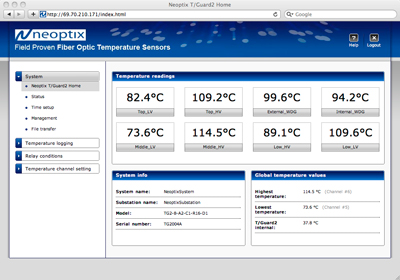
The T/Guard-2B system is delivered with a built-in 4GB data logging memory that allows utilities and transformer operators to record temperature data points and alarm status information directly into their T/Guard-2B temperature monitoring system, without the need for permanent connection to a remote acquisition system. Four memory represents more than eighty years of data logging for a transformer instrumented with eight temperature probes. The information can be accessed through any web browser. Moreover, data points are saved with a time stamp that comes from the internal real-time clock of the T/Guard-2B system.
The T/Guard-2B system is easy to interface to an existing marshaling or substation system through its 4-20 mA analog outputs (0-10 Volts user selectable) or its MODBUS communication interface or other optional smart protocols. RS-485 communication is standard. The T/Guard-2B is Ethernet savvy and incorporates the newest IEC-61850 protocol as an option. Information collected by the system can also be accessed through any web browser using TCP/IP.
With its small footprint, the T/Guard-2B is a space-efficient instrument. It is specifically designed to be installed inside the control cabinet; no need to add a large supplementary enclosure to protect the system. The T/Guard-2B can also be delivered with DIN rail mount brackets for a clean and streamlined layout.
The T/Guard-2B system has 16 Form-C (SPDT) industrial relays with galvanic isolation that can also be set up as Form-A or Form-B relays by user. The system has a fail safe mode whereby relays can be activated in case of system problem.
System's configuration is made through the industrial grade front panel keypad, serial terminal or the built-in web-based server.
Literature/images
LITERATURE
For a product brochure of the T/Guard-2B Signal Conditioner, please contact Neoptix
Accessories
Specific accessories specifically designed to complement and enhanced your T/Guard-2B System:
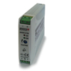
DIN Rail mountable power supply (Part: TG2-DPS)
DIN rail mountable 24 VDC universal (90-240VAC @ 47-63 Hz or 110~370 VDC), 2.5A, power supply for your T/Guard Signal Conditioner.
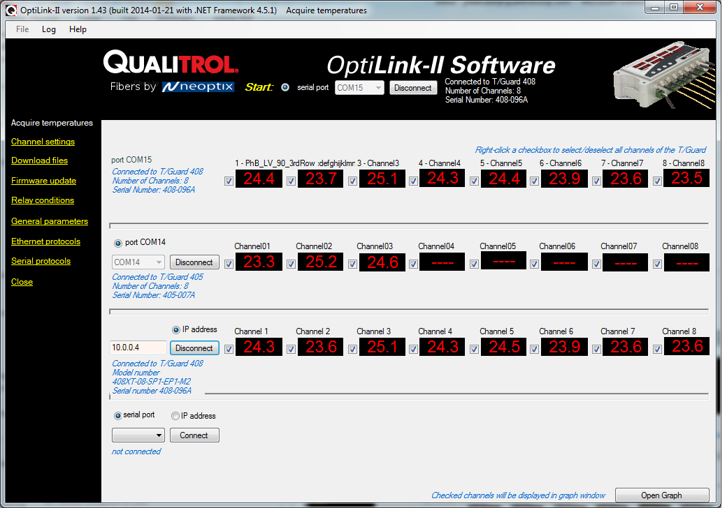
OptiLink Software (Part: NEO-LNK)
OptiLink control and datalogging software for the standard T/Guard 408 signal conditioner
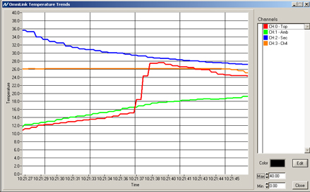
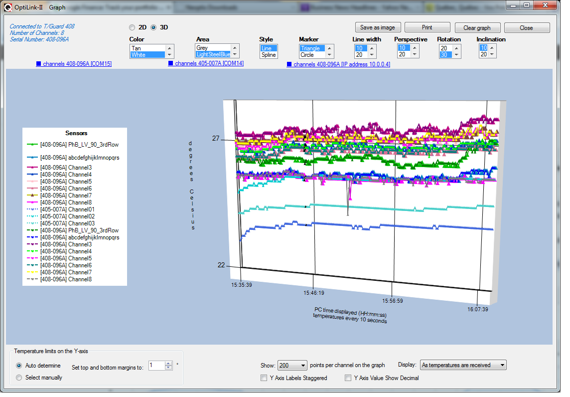
OptiLink-II Software control and datalogging software